Material processing has always been intertwined with the machine technology. Conventional machines were able to process materials such as metals in a satisfying way. However, there are limits to those conventional manufacturing processes. Such limits can be seen in the processing of amorphous metals, also known as metallic glasses. Therefore, a new technology like the additive manufacturing technology can further improve material processing. Electron beam melting (EBM) is such an additive manufacturing technology that has promising functionalities. Bulk metallic glasses (BMGs) exist in a wide range of alloy systems. Compared to conventional metals and alloys, metallic glasses show superior physical and chemical properties due to their amorphous structure. The fabrication of such alloys also promises materials with outstanding mechanical properties [1] [2] [3]. Therefore, they are considered as candidates for the next generation of structural materials [4]. BMGs have, for example, been reported to exhibit extremely high strength, high thermal stability, hardness and high corrosion resistance [5]. However, BMGs are difficult to manufacture due to relatively high required cooling rates for amorphous solidification. Zr-based glassy alloys, for example, show good glass forming abilities at relatively low required cooling rates. Therefore, an amorphous metal powder consisting of the elements zirconium (Zr), copper (Cu), aluminum (Al) and Niobium (Nb) was used and processed by electron beam melting. Thereby, the main objective is to set up a reliable process for sintering and melting with the EBM system. Zr-based BMGs have already found applications in the industries only three years after their invention [6] [7]. However, the achievable size of BMGs with solidification techniques is still quite small with diameters of only a few centimeters [8]. This limits extensive practical applications of BMGs. There have been successful results in welding, brazing and surface modification of amorphous metals with an electron beam [9] [10] [11]. However, generating large sized components from amorphous metal powder with EBM has not yet been successfully realized. In order to overcome this limitation, the development of appropriate manufacturing techniques is imperative. Additive manufacturing processes should be a good alternative. In this case the electron beam melting technology provides a good alternative.
For a stable electron beam melting process the powder is required to be sintered before fully melting the material. The sintering process needs to be to a degree in which the particles are anchored to each other but also without losing its morphological integrity. This is due to the fact that the residual sintered powder needs to be recovered in order to reuse it in the future. Parameters such as energy input, focus and scanning velocity control the sinter process.
The aim is also to further understand the correlations between applied scan velocity, energy input and focus offset in regard to the material properties of the metallic glass.
However, to find feasible parameters for the EBM process with this material, the parameters need to be adjusted in order to avoid process defects. Therefore, as a first step a sintering process needs to be carried out in order to mitigate or rather eliminate such defects. The sintering process is an integrated function within the EBM process to densify the loose powder in order to create a better structure for thermal and electrical conductivity. Figure 1 depicts the sintering process that occurs during the build.
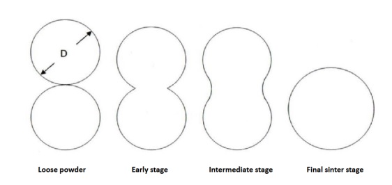
Figure 1: Different stages of sintering two spherical particles [13]
Theoretically, the electron beam melting can be divided into six main factors of influence that are presented in Table 1. The results of the EBM are dependent on the interaction of many parameters, whereas the impact of the parameters varies. The properties of the part are mostly determined by the beam current and diameter as well as the scan speed and the scanning direction. Besides the beam current and scan speed the layer thickness is also considered as critical parameter.
Table 1: Influencing factors of the electron beam melting process [14]
|
Material |
Part |
Powder layer |
Electron beam |
Built chamber |
Hatching |
|
Grain size and distribution |
Geometry |
Thickness |
Beam current |
Vacuum |
Scan speed |
|
Viscosity |
Orientation in the built chamber |
Powder density |
Intensity distribution |
Start plate |
Number of repetitions |
|
Properties (thermal, mechanical) |
Preheat-temperature |
Beam diameter |
Offset (focus and line offset) |
||
|
Scan direction |
It is known from literature that the results of EBM are affected by three main process defects. In order to obtain a stable sintering and melting process with EBM the defects are excluded by using matched parameters. The typical defect characteristics are outlined below.
One of the most common defects by EBM is spreading or pushing of the powder material. Immediately after hitting the powder bed by the electron beam the particles are accelerated and lifted up from the start plate explosively. This leads to a spreading of the particles across the building chamber and consequently to the abortion of the experiment.
The actual build-up process can be described as follows. First, the built chamber is heated up to a certain temperature to improve the build-up process. The powder is fetched from the powder hopper by a rake and a thin layer of powder is spread over the start plate. Afterwards, the powder is preheated by a defocused electron beam with comparatively low beam current and high scan velocity to sinter the powder slightly. That helps to hold the material in place during the melting process and to provide an even temperature distribution within the powder. This process occurs cyclic until the build is finished.
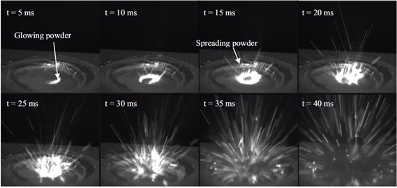
Figure 2: High speed photographs illustrating spreading of a single powder layer [15]
Furthermore, a phenomenon of delamination describes the result of a lack of micro connections between two adjacent layers. This may happen either during the construction process or after completely cooling of the part. Residual stresses encounter and remain inside the part, while it is in equilibrium with the environment. If there is no equilibrium it may cause delamination or deformations.
Another process defect can ensue during the melting process. If the powder material is not molten sufficiently with the previous layer, a formation of melt drops (“balling”) occurs. This is recognizable as spherical powder mergers on the surface. By this melt drops the finish quality is reduced.
The aim of this study is the processability of an amorphous metal powder with an EBM system.
For the experiments, a spherical pre-alloyed gas atomized amorphous powder with a composition of Zr70Cu24Al4Nb2 and a mean particle diameter of d50 = 65 µm was used. Figure 3 shows scanning electron microscope (SEM) images of the powder.
The system used for the experiments was the EBM A1 from the company Arcam AB, Sweden.
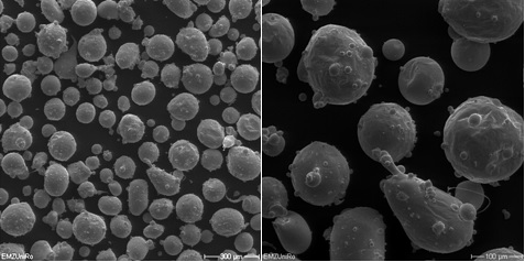
Figure 3: SEM image of the amorphous zirconium alloy powder
In order to enable a stable construction process of the Zr70Cu24Al4Nb2 powder alloy with a d50 of 62µm a design of experiments was conducted. This is an experimental parametric approach to obtain a stable and reproducible process with the EBM system. The method of the parameter variation was an iterative process.
At first, the parameter settings were chosen in order to establish a process that shows little to no defects. For the first test run the following parameter settings were chosen without heating the start plate and layer thickness of 125µm:
-
Scan speed of 12 m/s,
-
Beam current of 20 mA
-
Focus offset of 80 mA
The first test series was for a general evaluation of the used parameters and the results were evaluated visually and classified into “loose”, “lightly sintered” and “completely sintered” categories. Based on this classification the further progress of the experimental series was by narrowing down the parameter settings. Depending on the experiments the beam current was varied by 2 mA or the scan speed was varied by 2 m/s. As long as no sintered network of the particles was present the test series continued resulting in three further test series with different variations in scan speed as well as beam current.
The examinations of the samples were performed with the scanning electron microscope (SEM) “Merlin” from Carl Zeiss (Oberkochen, Germany).
Initially, the samples were assessed visually to get a first impression of the strength of the particle sinter cake. Represented samples are shown in Figure 4.

Figure 4: Effect of increasing the energy input either by increasing the beam current or by decreasing the scan speed, left: loose powder, center: lightly sintered powder, right: completely sintered powder
As depicted in table 2, test series 1 shows the influence of the scan speed on the sintering result with a constant beam current of 20 mA. Whereas in the test series 2 and 3 the scan speed remains constant at 8 m/s and 12 m/s while the beam current varies, accordingly.
After the initial test run, a systematic and iterative process was carried out with variations in the parameters scan speed and the beam current.
Table 2: Parameters of test series 1, 2 and 3 (macroscopic classification of the sintering results (1) loose powder, (2) lightly sintered powder, (3) completely sintered powder)

Already from the rough macroscopic assessment of the samples, a strong dependence of the sintering results from the above-mentioned parameters can be seen. The numbers (1) to (3) in Table 2 provide information on the macroscopic classification of the sintering results. To assess the microscopic structure, scanning electron micrographs of the samples from test series 1 are shown in Figure 5. The red circle shows patches of fully sintered powder within the loose powder bed.

Figure 5: SEM images of test series 1 (constant beam current of 20 mA), left: scan speed of 12000 mm/s (sample 1), center: scan speed of 8000 mm/s (sample 2), right: scan speed of 6000 mm/s (sample 3)
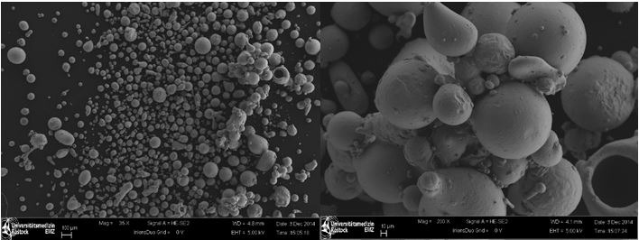
Figure 6: Sintering process of test series 2 (8m/s, 22mA) with particles still intact
In considering the SEM images of test series 2, which was performed with a scan speed of 8000 mm/s, marked morphological changes are visible. While in sample 2 the particles are still mainly loose (Figure 6), the particles get connected by increasing the beam power (Figure 7). It can be seen that the individual particle contours are not clearly visible anymore. This suggests that the intermediate sintering stage been exceeded. However, by narrowing down on the used parameter setting, a reliable sintering process of this alloy could be found.
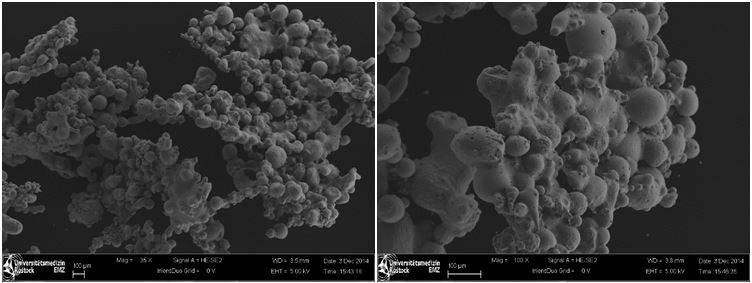
Figure 7: Sintering process of test series 3 (12m/s, 32mA) with lost morphology of particles
The parameter study resulted in a sinter cake that was densified enough for a stable energy input without spreading or rather pushing the particles. However, it was detectable that the applied powder layer was not uniform, leading to a tear-off of the layer. A reason could be found in the different sized particles. When passing larger particles with the rake, these particles get moved and consequently defects are formed. A schematic example is shown in Figure 8. If the differences between the particles is less this effect is rarely observed. Furthermore, the electron beam settings could also be the cause of a layer tear-off, if enough energy can’t reach the former layer in order to connect with the successive layer.
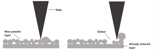
Figure 8: Defect in powder layer caused by larger particles
At a layer thickness of 250 μm, which corresponds to the maximum particle diameter, the effect of unconnected layers is enhanced. Even more energy is necessary to bind the powder layers together. However, more energy can counteract with the production of metallic glasses.
Furthermore, the powder contained many particles that had gas inclusions. These gas inclusions are originated by the gas atomization of the alloy. When the particles are heated up, the gas expands and the outer shell bursts. Thus the surrounded powder is moved by the explosive gas emission and the powder layer is destroyed. This failure can result in spreading of the powder or delamination. Figure 9 shows two examples for busted particles are presented.
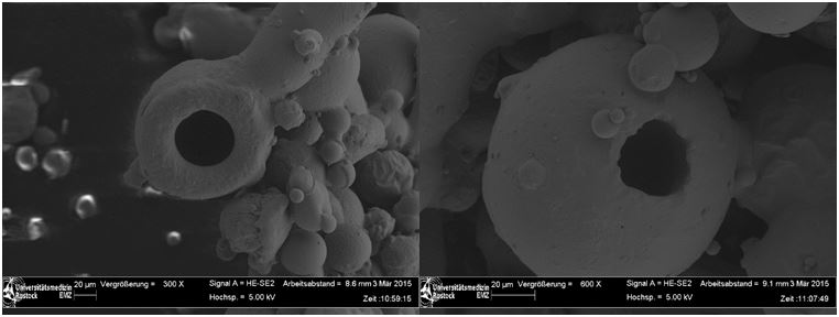
Figure 9: Gas inclusions that lead to busted particles by gas emission
However, despite the many obstacles of the process, parameter settings for a reliable sintering process of this alloy were established and a sinter cake with a thickness of 5 mm was created. By macroscopic examination of the sample interconnected layers were recognized. Even in the corners the layers were bonded together, as seen in Figure 10.
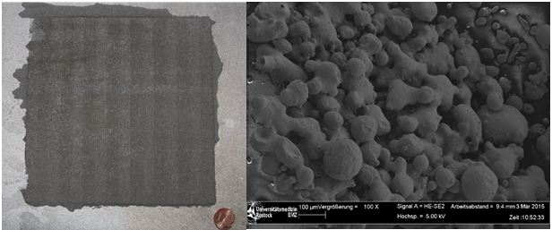
Figure 10: left: Sintered powder cake (parameters: Table 3), right: SEM image of the sinter cake
The adjustment of the parameter settings is restricted by the requirements of the amorphous metal powder. During the first sintering experiments the influence of three main parameters of EBM (beam current, focus offset and scan speed) on the processability of the metal powder was examined. It was revealed that the strength of the beam power and the scan speed is directly associated to the degree of the sintering of the amorphous metal powder.
In order to achieve a stable melt process with the EBM, a sufficient sintering process needs to be established to a certain degree without losing the amorphous structure. In order to find a stable sintering process, the influences of the process parameters such as beam current, focus offset, number of scan repetitions, and preheat-temperature on the sinter results need to be investigated in a parametric study. The scan speed, as well as beam current was chosen to be investigated. The parameters were adjusted iteratively. Consequently, parameter settings for a reliable sintering process of this alloy were established.
However, this study has shown that the sintering process still needs some adjustment to reach an optimization. Analysis such as x-ray diffractometry (XRD) and differential scanning calorimetry (DSC) can provide crucial information to better understand the mechanisms behind the parameter settings and the resulting thermal effects on the material. Throughout the investigation the process became more volatile when identical parameter settings led to different sinter results. Due to these results a chemical modification of the powder, caused by an unknown factor, is most likely present. Therefore, an oxygen analysis will be performed.
Further investigation needs to be carried out in order to fully understand the process and to create a stable process for manufacturing bulk metallic glasses with the electron beam technology.
[1] J. Lee, H. Kim, T. Kim, S. Shin, Y. Kim and J. Bae, "Deformation behavior of Ni-based bulk metallic glass synthesized by spark plasma sintering," Journal of Materials Processing Technology, vol. 187-188, pp. 801-804, 2007.
[2] H. Kim, J. Lee, S. Shin, H. Jeong, D. Kim and J. Bae, "Cu-based bulk amorphous alloys prepared by consolidation of amorphous powders in the supercooled liquid region," Intermetallics, vol. 12, 10-11, pp. 1109-1113, 2004.
[3] Y. Kawamura and Y. Ohno, "Successful Electron-Beam Welding of Bulk Metallic Glass," Materials Transactions, vol. 42, no. 11, pp. 2476-2478, 2001.
[4] E. Axinte, "Metallic glasses from ‘alchemy’ to pure science Present and future of design, processing and applications of glassy metals", Materials & Design, vol. 35, pp. 518-556, 2012.
[5] M. M. Trexler and N. N. Thadhani, "Mechanical properties of bulk metallic glasses," Progress in Materials Science, vol. 55, no. 8, pp. 759-839, 2010.
[6] W. L. Johnson, "Bulk Amorphous Metal - An Emerging Engineering Material," JOM, pp. 40-43, 2002.
[7] M. Telford, "The case for bulk metallic glass," Materials Today, pp. 36-43, 2004.
[8] W. Wang, C. Dong and C. Shek, "Bulk metallic glasses," Materials Science and Engineering. R, Reports: A Review Journal, vol. 44, pp. 2-3, pp. 45-89, 2004.
[9] Kagao, Shinya; Kawamura, Yoshihito; Ohno, Yasuhide: Electron-beam welding of Zr-based bulk metallic glasses. In: Materials Science and Engineering: A 375–377, pp 312–316, 2004
[10] Jonghyun Kim, Y. Kawamura, Electron beam welding of the dissimilar Zr-based bulk metallic glass and Ti metal, Scripta Materialia, Volume 56, Issue 8, , pp 709-712, 2007
[11] C.L. Li, J.W. Murray, K.T. Voisey, A.T. Clare, D.G. McCartney, Amorphous layer formation in Al86.0Co7.6Ce6.4 glass-forming alloy by large-area electron beam irradiation, Applied Surface Science, Volume 280, pp 431-438, 2013
[13] Zäh, Michael; Hagemann, Florian (2006): Wirtschaftliche Fertigung mit Rapid-Technologien. Anwender-Leitfaden zur Auswahl geeigneter Verfahren. München: Hanse
[14] Meindl, Matthias: Beitrag zur Entwicklung generativer Fertigungsverfahren für das Rapid Manufacturing. PhD Thesis. Technische Universität München, München, 2004
[15] Sigl, M.; Lutzmann, S.; Zaeh, M. F.: Transient Physical Effects in Electron Beam Sintering. In:Solid freeform fabrication symposium proceedings, vol. 17, pp 397-405, 2006
Dipl.-Ing Philipp Drescher
Universität Rostock
Lehrstuhl für Fluidtechnik und Mikrofluidtechnik
Justus-von-Liebig-Weg 6
18059 Rostock
E-Mail:
philipp.drescher@uni-rostock.de
WEB:
lfm.uni-rostock.de
Prof. Dr.-Ing Hermann Seitz
Universität Rostock
Lehrstuhl für Fluidtechnik und Mikrofluidtechnik
Justus-von-Liebig-Weg 6
18059 Rostock
E-Mail:
hermann.seitz@uni-rostock.de
WEB:
lfm.uni-rostock.de