Untitled Document
© 2015 Bremen, Sebastian; Lizenznehmer RTejournal, weitere Informationen sind zu finden unter: http://www.dipp.nrw.de/service/dppl/
urn:nbn:de:0009-2-42900
Profile extrusion is an established process for the continuous mass production of plastics profiles. The key element of an extrusion line is the extrusion die, which has the task to shape the melt delivered by the extruder into the desired profile [1]. To date, the design and manufacture of the die and its flow channel is characterized by extensive running-in trials and subsequent reworking steps. This leads to high fixed-costs in the design and manufacture of extrusion dies [2]. A promising approach to decrease the necessary amount of running-in trials consists in the incorporation of numerical flow simulations into the design of the die before its manufacture [3].
A numerical optimization, however, often leads to complex, free-formed flow channels [4, 5]. This imposes a major challenge to the manufacturing of the die which is usually done by milling or wire-eroding [1]. These processes reach their limit in case of dies with free-formed flow channels and lead to high manufacture costs. Depending on the complexity of the flow channel geometry, it may even be that conventional processes are not applicable at all. Here additive manufacturing processes can provide remedy, in which the product, in this case the extrusion die, is manufactured without a die or mould by layer-wise application of material [6]. The decisive advantage in the additive manufacturing of extrusion dies is the possibility to economically manufacture arbitrarily shaped flow channels, particularly ones with free-formed geometries. Furthermore, additive manufacturing processes enable a monolithic die design. Currently, profile extrusion dies usually consist of multiple, screwed together slices in which the respective flow channel sections are incorporated [5]. This slice design is necessary in order to produce and rework the complex flow channel geometry in conventional processes. In additive manufacturing of the die, however, the die can be built as a single part even in case of a free-formed flow channel. Thereby the costs for the die manufacture can be decreased and the die quality can be increased as there are less parting lines in the die where melt could leak out. Another advantage of additive manufacturing processes is that additional functional elements such as geometrically adapted tempering channels can be integrated into the die without additional process steps.
An especially promising additive manufacturing process for metal parts is the Selective Laser Melting (SLM). With this process metal parts with series identical mechanical properties can be produced without the need for part specific tooling or downstream sintering processes [7]. Against this background, the use of dies manufactured by SLM in the plastics profile extrusion is being investigated as part of the Cluster of Excellence “Integrated Production Technologies for High-Wage Countries” at RWTH Aachen University. The focus of the following investigations is hereby to ensure a sufficient surface quality of the profiles that are produced with the additively manufactured die.
The ILT-developed additive manufacturing technology Selective Laser Melting (SLM) makes it possible to manufacture metal and ceramic components layer by layer according to a 3D-CAD model [8]. Thereby, the process enables the manufacturing of individual parts with nearly unlimited complexity without need of part specific tooling. [9] [10] [11]
The SLM process can be divided into the process steps illustrated in Fig. 1. The first step is the preparation of the geometrical data. Here the 3D-CAD model is broken down into layers (slicing) and the scanning vectors of the laser beam are defined. Subsequently, the powder material is deposited as a defined thin layer on a substrate. The geometric information of the sliced CAD-model is transmitted by laser beam to the powder bed wherein the regions to contain solid material are scanned under an inert gas atmosphere, leaving a solid layer of the piece to be produced. After lowering the platform by one layer thickness, the process steps are repeated until the part is finished. [8, 12, 13].
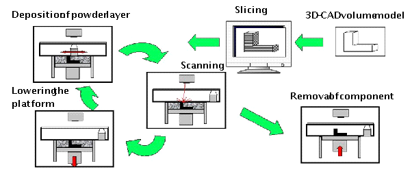
Fig. 1 Principle SLM process
According to the current state of the art SLM is already used to manufacture tools for the die-casting process out of tool steels (e.g. 1.2709) for small series. Thereby the SLM technology enables the integration of cooling channels with almost unlimited geometrical freedom. As a result existing hot spots in the die casting tool can be reduced and an improved tool cooling can be realized. Thus, the cycle time for die casting can be reduced. Research activities in this field focus on the improvement of the surface roughness within the cooling channels to improve flow ability of the cooling liquid as well as on the calculation and simulation of the temperature distribution of SLM manufactured die-casting tools. [20] [21]
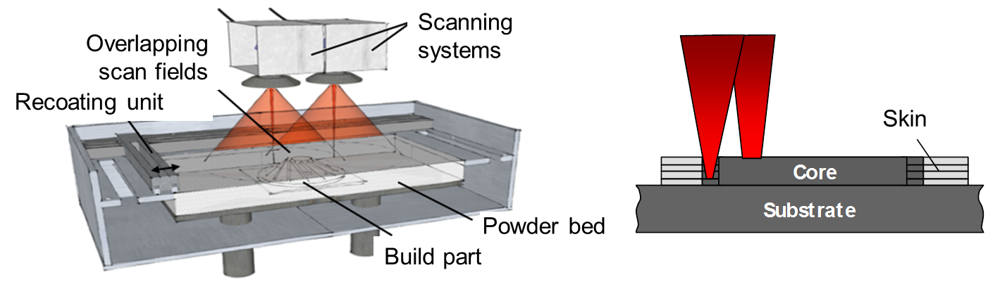
Fig. 2 Principles of productivity improvement for the SLM process: a) Parallel use of multiple laser sources b) High Power SLM with skin-core strategy
Nevertheless, the productivity of the SLM technology is the most important barrier in order to pave the way to a cost efficient production of tools with higher lot sizes [7]. A value for the productivity of the SLM process is the theoretical build up-rate which can be calculated by the product of scanning velocity, hatch distance and layer thickness. In order to increase the theoretical build-up rate two principle concepts are used and offered in commercial SLM machines (Fig. 2) [14, 15].
The first concept to increase the productivity of the SLM process deals with the simultaneous use of multiple laser beam sources in a SLM process. Thereby the time to melt up one layer can be linearly reduced by the number of laser sources used. The second concept is to increase the laser power and thereby the energy input in the powder bed. By adaption of the process parameters scanning velocity and layer thickness the theoretical build-up rate can be increased for materials with high heat conductivity (e.g. aluminium alloys λ=120-150 W/(mK)). For materials with a heat conductivity in the range between λ=5-30 W/(mK) the increased energy input and the significantly increased intensity leads to evaporation of the material and spattering. This results in an unstable and non-reproducible SLM process. Therefore, the Fraunhofer ILT has developed the so called skin-core strategy, whereby the part is divided into an inner core and outer skin [9]. Different process parameters and beam diameters can be designated to each area. The core does not have strict limitations concerning the accuracy and detail resolution. Therefore, the beam diameter can be increased (ds≈400-1000 µm) and increased laser power can be employed in order to heighten the theoretical build-up rate. In contrast the skin area is processed with a laser power PL ≤ 400 W and a small beam diameter (ds≈60-200 µm) as well as a layer thickness in the range of Ds=30-50 µm to assure an improved accuracy and surface quality.
As a test case for additively manufactured extrusion dies a die for the production of a L shaped plastics profile is manufactured in the SLM process. The flow channel of this die was numerically designed with the help of a newly developed software framework for the automated optimization of extrusion dies [4]. The design criterion is hereby to achieve a homogeneous velocity distribution at the outlet of the flow channel. The resulting flow channel of the die possesses several free-formed geometry features (Fig. 3). These are the geometry features inlet, edge and side, all of which serve to homogenize the velocity distribution at the die outlet.
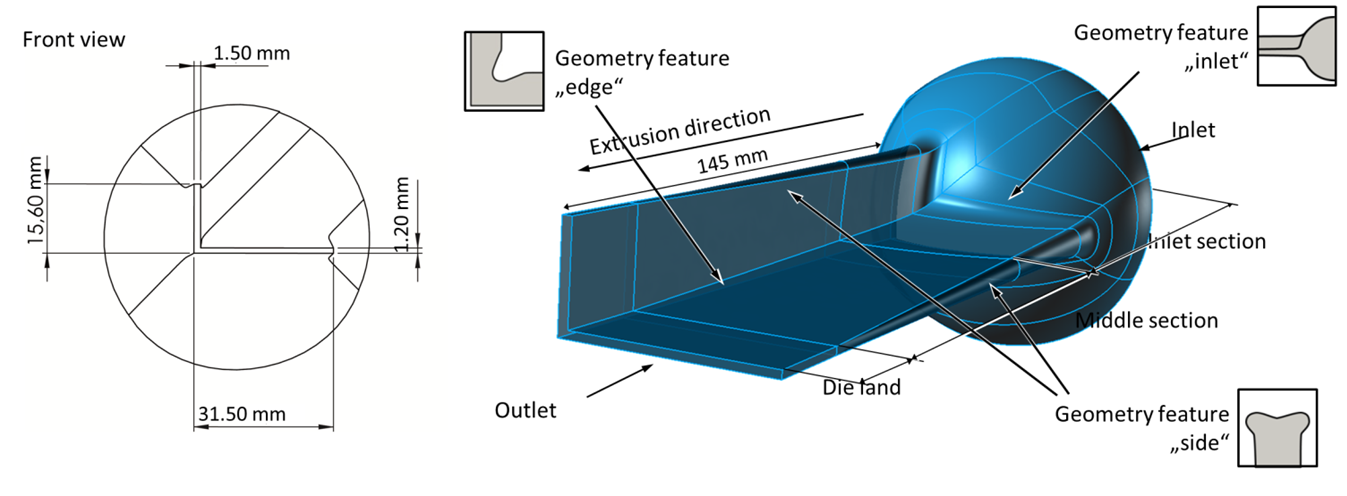

Fig. 3 Automatically optimized flow channel for the production of a L-shape profile
The flow channel possesses a die land with a length of 15 mm. The designed die has also been manufactured by milling and its flow channel has been reworked by polishing in order to validate the simulative die optimization [16]. In this case, the manufacture of the die by milling was possible in spite of the free-form geometries, as the L-profile die possesses a relatively simple flow channel. However, industrially relevant profiles are much more complex than the investigated L-profile. Therefore, the flow channel geometry in the corresponding dies will also be much more complex. In such cases, the manufacture of automatically optimized dies with free-form flow channels by conventional means will not be feasible and additive manufacturing processes like the SLM will be required.
The powder material used for the investigations is the maraging tool steel 1.2709 (X3NiCoMoTi18-9-5) with a grain size between 15-45 µm. Maraging steels are iron nickel alloys with absence of carbon and contain additional alloying elements such as molybdenum, cobalt, titanium or aluminium. The structural hardening is obtained by intermetallic phases between nickel and the alloying components (Co, Mo, Ti). Thus, these steels are characterized by ultra-high strength, superior toughness, good weldability and low distortion. [17].
Before the L-profile die can be manufactured with High Power SLM, process parameters for the skin and core area have to be evaluated. For the manufacture of the die the High Power SLM machine SLM 280HL (SLM Solutions) with two different beam diameters is used. Beamway 1 with a beam diameter of ds1=70 µm (Gaussian beam profile) is used to process the skin area at PL1=300 W and a layer thickness of Ds=30 µm. Thereby a theoretical build-up rate of Vth=2.9 mm³/s can be achieved.
For the manufacture of the core area of the L-profile beamway 2 is employed (ds2=720 µm) at a laser power of PL2=1 kW and a constant layer thickness of Ds=90 µm. In order to investigate a process window which allows to build up the core area with an average density ρ ≥ 99.5 % cubic test specimens are produced by variation of scanning velocity and hatch distance.
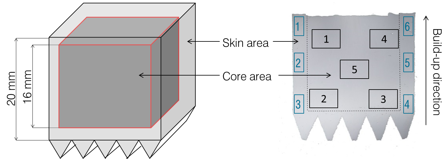
Fig. 4 Geometry of test specimens and cross-section with measuring fields
After the SLM process cross-sections are made and the density is measured by arithmetic averaging of the results from 5 measurement fields per test specimen in skin and core area (Fig. 4). The averaged measured density according to the scanning velocity and hatch distance is shown in Fig. 5. It can be observed that for a hatch distance of ∆ys=400 µm test specimen with an average density ρ ≥ 99.5 % can be manufactured up to a scanning velocity of vscan=400 mm/s. For this parameter set a theoretical build-up rate of Vth=14.4 mm³/s is achieved. A further increase of the hatch distance leads to reduction of the scanning velocity in order to produce dense parts. . According to these results the parameter set at ∆ys=400 µm with a scanning velocity of vscan =400 mm/s is chosen to build up the core area of the L-profile die.
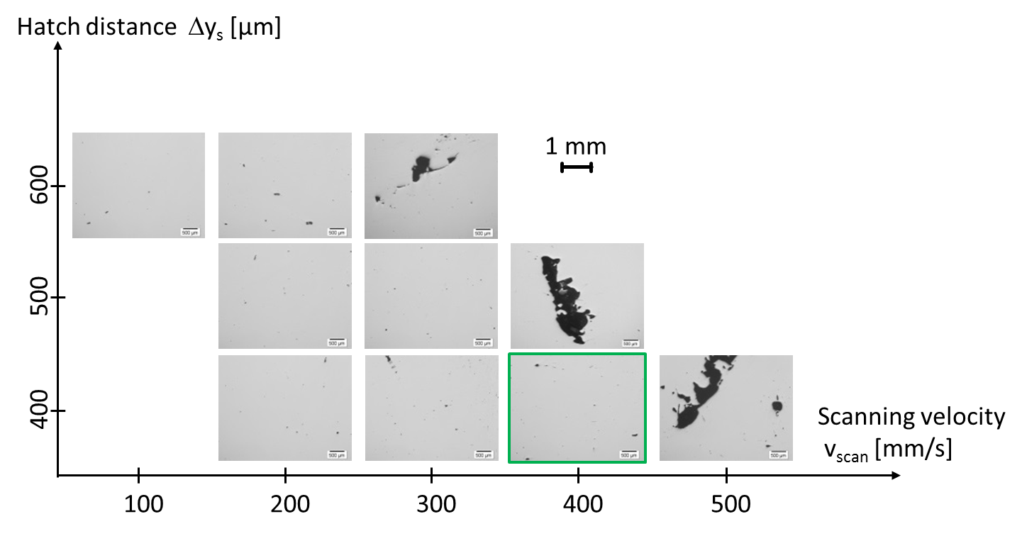
Fig. 5 Cross section of test specimens according to hatch distance and scanning velocity (PL=1 kW, BW2, Ds=90 µm)
According to the SLM process chain (Fig. 1) the CAD data of the L-profile die has to be prepared for the SLM process. Hereby the software divides the part into an inner core and an outer skin with a skin width of b=2 mm (Fig. 6). The L-profile die consists of two parts: a three-quarter part which is shown in Fig. 6 and a matching quarter-part. For the presented investigations only the three-quarter part was manufactured by SLM, which was combined with the conventionally manufactured quarter-part from [17] for the extrusion trials described in chapter 4. The reason for this was to keep the production time of the first test die as short as possible. The volume of the whole three-quarters part of the L-profile die is calculated to approximately Vges=1028 cm³. Using the skin and core strategy the core volume is calculated to Vcore=800 cm³ and the skin area is calculated to Vskin=228 cm³.
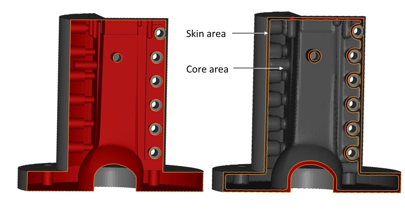
Fig. 6 CAD-model of the die prepared for SLM process (left: conventional SLM, right: skin core strategy)
Manufacturing the three-quarters part of the L-profile die with conventional SLM (PL=300 W, Ds=30 µm), a theoretical build-up rate of Vth= 2.9 mm³/s can be achieved. Applying HP-SLM (PL=1 kW, Ds=90 µm) and the adapted skin-core strategy, the theoretical build-up rate for the core can be increased up to Vth= 13.5 mm³/s. The overall theoretical build-up rate, which depends of the ratio between the volume of skin and volume of core area, is calculated to Vth=11.12 mm³/s. This is a significant increase by factor of 3.8 in comparison to conventional SLM.
The theoretical build-up rate is a calculated approach to compare the productivity of the SLM process based on the employed main process parameters. Far more interesting is a comparison of the production times for the manufacture of the die by conventional SLM (PL=300 W, Ds=30 µm) and High Power SLM (PL=1 kW, Ds=90 µm).
When analyzing the production time for the two build-up strategies it becomes evident that the time which is necessary to melt up the powder material can be decreased significantly by employing the skin-core strategy. Employing the process parameters for conventional SLM the manufacture of the three-quarters part of the L-profile die takes approximately 97 hours. By increasing the laser power up to PL=1 kW and use of the skin-core strategy the production time can be decreased by approx. 46 % down to 52.5 h. It can be observed that the increase of laser power by a factor of approx. 3.3 is not completely transferred into a reduction of the processing time by an identical factor. The increase of the laser power effect only the primary processing time whereas the auxiliary time is constant. All in all, these investigations show that for geometries with a large volume, such as dies for profile extrusion dies, an increased laser power can be used to significantly decrease the production time. Thereby the most important obstacle of the SLM process, which is the low productivity of the SLM process, can be removed. Following another barrier of the SLM process, which is the surface roughness and the influence on the resulting product properties, is investigated in detail.
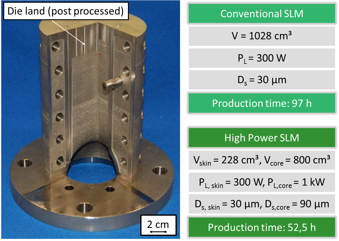
Fig. 7 SLM manufactured three-quarters part of the L-profile die and main process parameters and production time
An important challenge in the usage of additively manufactured profile extrusion dies is the surface quality of the die. In general, high optical and haptic requirements are placed on plastics profiles. In order to achieve the desired smooth surface of the extruded profile, a high surface quality in the flow channel of the die is required which is usually achieved by polishing. The sealing surfaces of the die are usually grinded. The conventional requirement for the roughness is hereby Rz ≤ 1 µm in the flow channel and Rz ≤ 4 µm at the sealing surfaces [18]. By contrast, parts manufactured by commercial SLM machines possess a roughness Rz of at least 20 µm for 1.2709 [19]. This difference in surface quality can also be observed in the extrusion die. Fig. 8 shows silicon impressions of the flow channel surfaces of both the conventionally and additively manufactured die, which were examined with a laser confocal microscope type VK-X200 of the company Keyence Deutschland GmbH, Neu-Isenburg, Germany. Silicon molds were used as a direct examination of the die surface is not possible due to the limited space of the microscope. It should be noted, that it is not possible to take perfect impressions of the surfaces with the silicon due to its viscosity. Because of this the measured Rz values differ from the ones mentioned in [18] and [19]. In any case the surface of the SLM die has a much lower quality than the conventionally manufactured die.
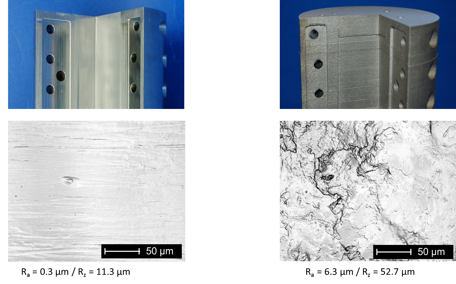
Fig. 8 Flow channel surface of the conventionally manufactured die (left) and the additively manufactured die (right)
Accordingly, a reworking of the flow channel surface is also required in case of the additively manufactured extrusion die in order to ensure a satisfactory profile surface quality of the. However, since the additive manufacturing of the die is especially suited to cases with free-formed channels, the polishing of the entire flow channel should be avoided. Rather, a concept for surface finishing needs to be found, which on the one hand ensures a sufficient surface quality of the produced profiles and on the other is applicable to arbitrarily shaped flow channels.
A promising approach is to only rework the die land of the flow channel, which is the last part of the flow channel immediately before the die outlet. The die land possesses in comparison to the remaining flow channel a relatively simple geometry. Accordingly, this area can be reworked conventionally with reasonable effort even in case of more complex profile geometries. At the same time, the die land is also the area that has the biggest influence on both the dimensional accuracy and surface quality of the extruded profile. This leads to the hypothesis that with a mere reworking of the die land with conventional processes, which is feasible for even complex profiles, a sufficient surface quality of the profiles produced can be achieved. This claim is examined in the following investigations.
For the investigation of the derived hypothesis extrusion trials are conducted with three different die setups: (a) the conventionally milled die, (b) the additively manufactured die with milled die land and (c) the additively manufactured die with polished die land. The sealing surfaces are milled both in case (b) and (c). The extrusion trials are conducted on a laboratory extrusion line consisting of an extruder, a calibrating unit and a take-off unit. The extruder used is a laboratory scale extruder 19/10DW by Brabender GmbH & Co. KG, Duisburg, Germany, with a diameter of 19 mm and a length of 25D. For the calibration of the extruded profile a vacuum-assisted calibrator in a water bath is used.
In the extrusion trials several process points are examined for each die setup, whereby the mass throughput (1.4 kg/h, 1.7 kg/h, 2 kg/h) and the die temperature (225 °C, 230 °C, 235 °C) are varied. The mass temperature at the die inlet is set identical to the die temperature in each test point. The material used for the investigations is Polypropylen Moplen HP400H of the company Basell Polyolefine GmbH, Frankfurt am Main, Germany.
After the extrusion trials the surface of the produced profiles are analyzed with a laser confocal microscope type VK-X200 of the company Keyence Deutschland GmbH, Neu-Isenburg, Germany. The microscope is used both for the recording of microscopic surface images and the measurement of the profile surface roughnesses. For each test point at least four profile samples are examined microscopically. The roughness values of each test point are then obtained as the average over the four samples.
Influence of the process parameters on the profile roughness
In the first step the influence of the process parameters on the roughness of the profile surfaces is analyzed. Fig. 9 shows the average roughness of the profiles manufactured with the conventional die at different process points.
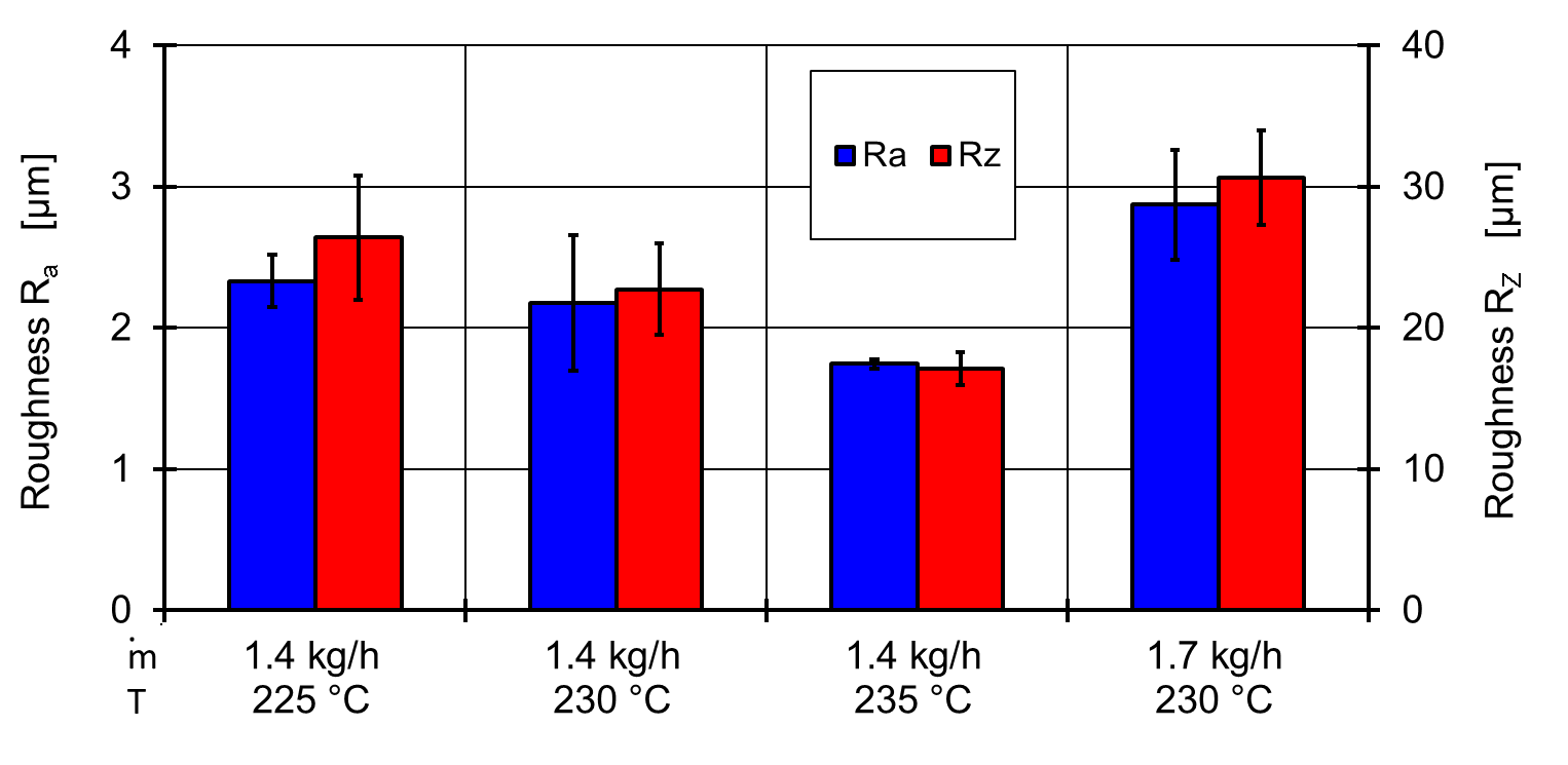

Fig. 9 Average roughness values of the profiles manufactured with the conventional die (a)
The roughness increases with decreasing melt temperature and increasing throughput. For example, a decrease of the temperature from 235 °C to 225 °C increases the value of Ra by about 0.59 µm. By contrast an increase of the throughput from 1.4 kg/h to 1.7 kg/h increases the Ra value by 0.54 µm. These observations can also be seen in the other die setups and can be explained if one considers how the roughness of the profile surface is formed: While flowing through the flow channel of the die, the plastics melt is pressed against the rough channel surface due to the internal pressure in the die. Thus, the surface of the melt is embossed by the rough flow channel surface. This roughness can further increase after the die exit due to the swelling of the profile. In the following vacuum-assisted calibration, however, the roughness peaks of the profile surface are partially smoothed.
Using this model, the influence of the process parameters can now be explained: In case of the melt temperature an increase of this parameter leads to a decrease of the melt viscosity. This results on the one hand in a better replication of the protrusions in the flow channel by the melt, which lead to roughness peaks on the profile surface. On the other hand, a higher mass temperature also means a lower viscosity at the inlet of the calibrator so that the smoothing effect of the calibration is also improved. Assuming that the smoothing effect of the calibration is more strongly affected by the melt temperature than the replication of the flow channel surface by the melt, this leads in sum to the decrease of Ra with increasing melt temperature.
An increase of the mass throughput also leads to a better replication of the rough flow channel surface by the melt due to the higher internal pressure in the die. At the same time, the increased flow rate causes a reduced residence time in the calibration, so that its smoothing effect is reduced. The result is an increasing roughness with increasing throughput.
The comparison of the roughness parameters Ra and Rz shows that the values of Rz are always higher than the ones of Ra. Hereby, the Rz value is in all examined test points approximately ten times as large as the Ra value. Of particular importance is that the above-described statements regarding the influence of the process parameters on the profile roughness retain their validity even when considering Rz instead of Ra. Thus, Rz also increases with increasing mass throughput or decreasing melt temperature. Accordingly, both parameters are suited for the following comparison of the different die setups.
Comparison of the conventionally and additively manufactured dies
Fig. 10 shows the measured roughness of the profiles obtained with the different die setups. Firstly, it can be seen that in every die setup the varied process parameters affect the profile roughness in the same way.
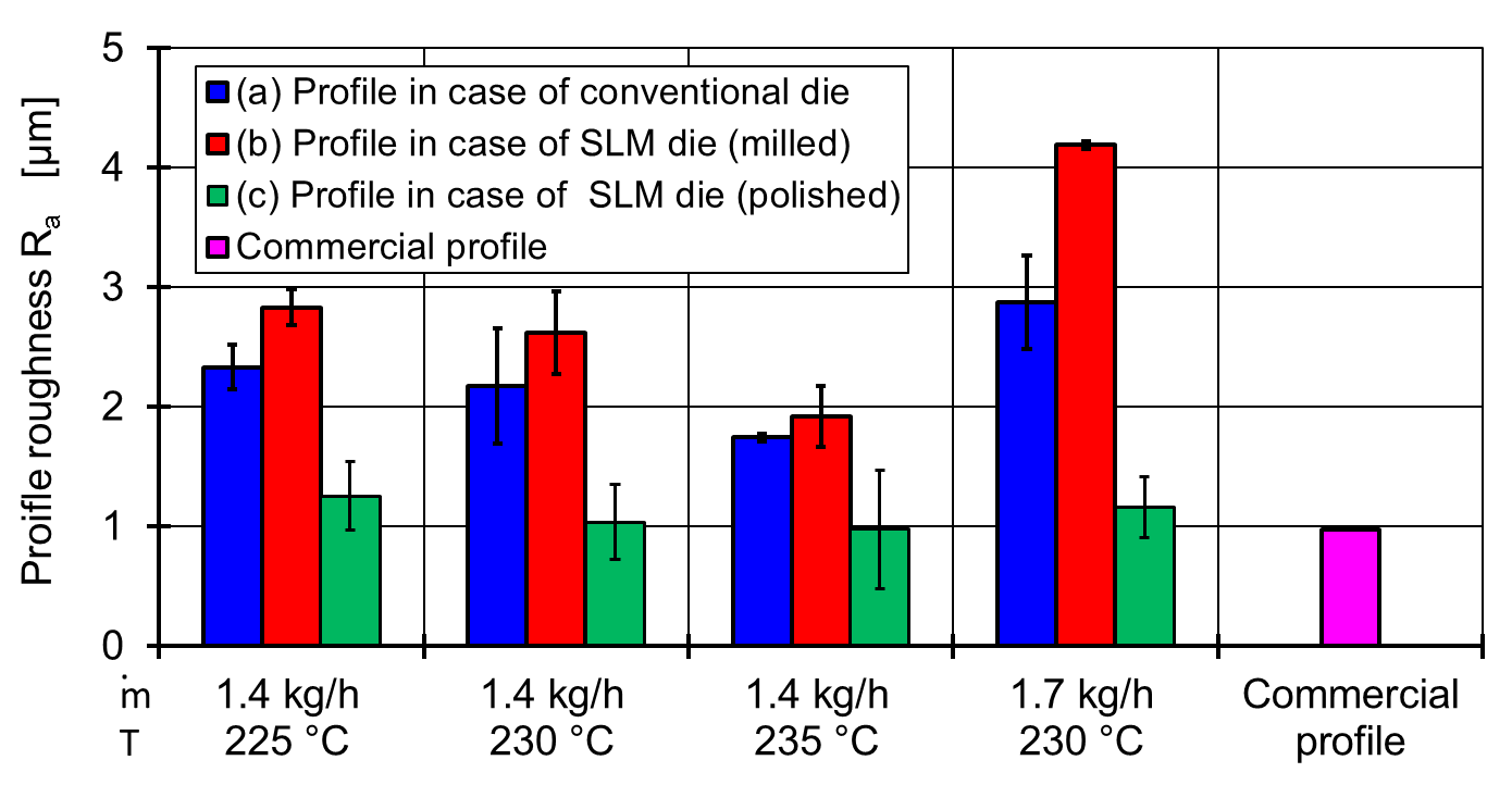

Fig. 10 Average roughness Ra of the profiles manufactured with different die setups
Here, too, an increase of the throughput or a reduction of the melt temperature leads to an increase of the profile roughness. When comparing the conventional die (a) and the SLM die with milled die land (b), it can be seen that the roughness of the profile surfaces are comparable for both dies and are in the same order of magnitude. However, the profile roughness is in case (b) always slightly higher than in case (a). The reason for this is that the milled die land of the SLM die has a lower surface quality than the conventional die, which has a polished die land. Measurements on silicon molds from the die lands deliver a roughness of (Ra=0.3 µm/Rz=11 µm) for (a) and a roughness of (Ra=1.5 µm/Rz=31 µm) for (b). In total, this means that SLM dies with milled die lands are generally suitable for applications with low requirements on the surface quality. For profiles with high optical and haptic requirements, however, an improvement of the die surface quality is necessary; especially considering that the influence of the process parameters on the profile roughness is much more pronounced in case of the SLM die with milled die land than in case of the conventional die. In industrial practice the highest possible throughput and low melt temperatures are desirable from an economic contemplation. Accordingly, the differences in profile surface quality between the conventionally and additively manufactured die should be greater in the industrial practice than in the presented studies.
The required improvement of the surface quality can be achieved when the die land of the SLM die is not only milled, but also polished (c). Fig. 10 shows that this leads to a significant improvement of the profile surface as compared to the case with the milled die land (b). Hereby, not only the values of Ra and Rz, but also their dependency on the process parameters decreases significantly so that they are nearly independent of the operating point within the investigated process window. It is particularly interesting that the roughness of the profiles, which are produced with the SLM die with polished die land, is comparable with the roughness of a commercial profile, which was measured as a reference (Fig. 10). The manufactured profiles in (c) thus have a surface quality suitable for industrial applications.
When comparing (a) and (c), it is noticeable that the profiles produced with the SLM die have a better surface finish than when using the conventional die. This observation, however, cannot be generalized: The smaller roughnesses in case (c) are entirely due to the fact that in the conducted investigations the surface quality of the polished die land of the SLM die is higher than the one of the conventional die. Measurements of silicon molds from the die lands result in a roughness of (Ra=0.1 µm/Rz=7.4 µm) in case of the SLM die and a roughness of (Ra=0.3 µm / Rz=11 µm) in case of the conventional die. Accordingly, since the SLM die has a better polished die land than the conventional die, case (c) leads to smoother profile surfaces (Fig. 11).
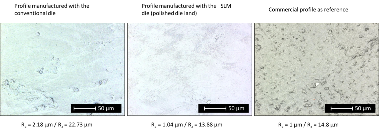
Fig. 11 Comparison of the surfaces of profiles manufactured with different die setups
In conclusion, the investigations confirm the hypothesis that the surface quality of the extruded profiles is mainly influenced by the surface finish of the die land and less by the rest of the flow channel. Therefore profile extrusion dies manufactured by SLM can be used without negatively affecting the surface quality of the produced profiles as long as the die land is polished.
The goal of the presented work is to show the fundamental applicability of additively manufactured dies in plastics profile extrusion. For this purpose, a die for the manufacture of a L-shaped profile was successfully manufactured by High Power Selective Laser Melting. By the use of increased laser power and the skin-core strategy the production time could be decreased by 46 % in comparison to the conventional SLM process. Afterwards the application of the die in the extrusion process was analyzed with focus on the surface quality of the profiles manufactured with such dies. In order to achieve a sufficient profile surface quality a suitable reworking of the die, which is feasible for arbitrarily shaped flow channels, is necessary. The chosen approach for this was to only rework the die land of the flow channel by milling or polishing. Profiles were manufactured with a conventionally manufactured die and the SLM die with both milled and polished die land. The comparison of profile surfaces shows that the reworking of the die land is sufficient in order to achieve a good profile surface quality even with the SLM die. In case of the milled die land, the profiles of the SLM die have a slightly worse roughness than the ones from the conventional die. This method for die reworking is therefore only suitable for applications with lower requirements to the profile surface. However, in case of the SLM die with polished die land the achieved profile surfaces have the same quality as the ones from the conventional die. Therefore, SLM dies can be applied in profile extrusion without disadvantages regarding the profile surface as long as the die land of the flow channel is polished after the SLM process. However, it should be noted that in case of plastics other than Polypropylene the rough flow channel of the SLM die could lead to depositions which can negatively influence the surface quality of the extruded profiles. That is why the presented investigation should also be repeated with different materials.
An alternative approach for the surface finishing of SLM dies consist in the use of chemical-physical polishing processes which use the flow of a medium to smoothen the machining area. These processes can even be used to economically rework the whole flow channel in SLM dies. That is why in the next step the reworking of the flow channel of SLM dies by chemical-physical polishing will be investigated and compared to the polishing of the die land.
Another important topic, which will be addressed in future works, is the optimization of the die topology. The economic efficiency of the SLM process largely depends on the volume of the part being produced. To ensure the highest possible efficiency of the procedure, it is necessary to adapt the geometry of the die to its mechanical loads and minimize its mass.
[1] Michaeli W (2003) Extrusion Dies for Plastics and Rubber. Carl-Hanser Verlag, München, Wien
[2] Morton-Jones DH (1989) Polymer Processing. Chapman and Hall: New York
[3] Brecher C (2012) Integrative Production Technology for High-Wage Countries. Springer, Berlin
[4] Siegbert R, Elgeti S, Behr M, Kurth K, Windeck C, Hopmann C (2013) Design Criteria in the Numerical Design of Profile Extrusion Dies. Key Eng Mater 554-557: 794-800. doi: 10.4028/www.scientific.net/KEM.554-557.794
[5] Szarvasy I, Sienz J, Pitman J, Hinton E (2000) Computer Aided Optimisation of Profile Extrusion Dies. Int Polym Process 1: 28-39, doi: 10.3139/217.1577
[6] Gibson I. Rosen D, Stucker B (2015) Additive Manufacturing Technologies. Springer, Berlin
[7] Schleifenbaum S, Meiners W, Wissenbach K, Hinke C (2010) Individualized production by means of high power Selective Laser Melting. CIRP J Manuf Sci Technol 2: 161-169, doi:10.1016/j.cirpj.2010.03.005
[8] Meiners W, (1999) Direktes Selektives Lasersintern einkomponentiger metallischer Werkstoffe. Dissertation, RWTH Aachen University
[9] Schleifenbaum JH (2012) Verfahren und Maschine zur individualisierten Produktion mit High Power Selective Laser Melting. Dissertation, RWTH Aachen University
[10] Buchbinder D (2013) Selective Laser Melting von Aluminiumgusslegierungen. Dissertation, RWTH Aachen University
[11] Over C (2003) Generative Fertigung von Bauteilen aus Werkzeugstahl X38CrMoV5-1 und Titan TiAl6V4 mit Selective Laser Melting. Dissertation, RWTH Aachen University
[12] Schleifenbaum H, Diatlov A, Hinke C, Bültmann J, Voswinckel H (2011) Direct photonic production: towards high speed additive manufacturing of individualized goods. SPE Prod Eng 5: 359-371. doi: 10.1007/s11740-011-0331-0
[13] Gebhardt A (2013) Generative Fertigungsverfahren. Carl-Hanser Verlag, München
[14] SLM Solutions AG Home Page (2015) http://www.stage.slm-solutions.com/download.php?f=8b5999a5b984bae55c98d135df9d2a27. Accessed 9 Feb 2015
[15] EOS GmbH Home Page (2015) http://ip-saas-eos-cms.s3.amazonaws.com/public/9707ab19c3bbe78b/887aafba7af0ebf6ca74bc61c9108202/EOS_Systemdatenblatt_EOS_M_400_de.pdf. Accessed 9 Feb 2015
[16] Hopmann C, Eilbracht S, Windeck C, Yesildag N (2013) Numerical Analysis of Flow Phenomena in the Extrusion Process – A Review on Simulation Research at the IKV. ANSYS Conference & 31. CADFEM Users’ Meeting 2013, Mannheim, Germany, 19.06.2013
[17] Casalino G, Campanelli SL, Contuzzi N, Ludovico AD (2015) Experimental investigation and statistical optimisation of the selective laser melting process of a maraging steel. Opt Laser Technol 65: 151-158. doi: 10.1016/j.optlastec.2014.07.021
[18] Herne, KV (2002) Instandhaltung von Extrusionswerkzeugen. Plastverarbeiter 53 (2): 78-79
[19] Meiners W (2011) Selective Laser Melting – Additive Manufacturing for series production of the future? Intermat 2011, Luxembourg, 01.02.2011
[20] JANSEN S (2013) Generative Fertigung von konturnah temperierten Werkzeugen mittels Selective Laser Melting, Dissertation RWTH Aachen, Apprimus Verlag
[21] ARMILOTTA A, BARAGGI R, FASOLI S (2014) SLM for die casting with conformal cooling channels. International Journal for Manufacturing Technologies 71, S. 573-583
The depicted research has been funded by the Deutsche Forschungsgemeinschaft (DFG) as part of the program Cluster of Excellence “Integrative Production Technology for High-Wage Countries”. We would like to extend our thanks to the DFG.
Furthermore, we would like to thank the Basell Polyolefine GmbH, Frankfurt am Main, Germany, for the provided test materials and the Döllken Kunststoffverarbeitung GmbH, Gladbeck, Germany, for the reworking of the SLM die.
Prof. Dr.-Ing. Christian Hopmann, born 1968, is holder of the Chair of Plastics Processing at RWTH Aachen University and managing director of the Institute of Plastics Processing (IKV).
Nafi Yesildag, M.Sc., born 1988, is a scientific employee at the IKV since 2013 and works on the design of extrusion dies and CAE (Phone: +49 241 8027271, mail: nafi.yesildag@ikv.rwth aachen.de)
Dipl.-Wirt.-Ing. Sebastian Bremen, born 1983, is a scientific employee at the Fraunhofer Institute for Laser Technology (ILT) since 2011 and works on the additive manufacturing technology Selective Laser Melting (SLM); (Phone: +49 241 8906537, mail: sebastian.bremen@ilt.fraunhofer.de)
Dr. rer. nat. Konrad Wissenbach, born 1954, is head of department additive manufacturing and functional layers at Fraunhofer Institute for Laser Technology (ILT).
Dipl.-Wirt.-Ing. Simon Merkt, born 1986, is a scientific employee at the Chair for Laser Technology at RWTH Aachen since 2011 and works on the topic design for SLM ; (Phone: +49 241 8906658, mail: simon.merkt@llt.rwth-aachen.de)
Adress:
Institute of Plastics Processing, Pontstr. 49, 52062 Aachen, +49 241 80-93806
Fraunhofer Institute for Laser Technology ILT, Steinbachstrasse 15, 52074 Aachen, +49 241 8006-100