Fabrication of ceramics by stereolithography
© 2007 Christophe Chaput; Lizenznehmer RTejournal, weitere Informationen sind zu finden unter: http://www.dipp.nrw.de/service/dppl/
urn:nbn:de:0009-2-11635
Abstract
Rapid prototyping methods (RP) make it possible to elaborate 3-D complex architectures, without tooling or machining, directly on the basis of a computer aided design (CAD) file. These methods were developed first, about twenty years ago, with polymeric materials. Today, a large number of these RP processes are available to produce ceramic parts.
Among the various RP techniques, stereolithography (SLA) has been successfully adopted to the direct production of final useful ceramics parts with sintered properties similar to those obtained by classical processing techniques and with a good dimensional definition (100 µm). At the present, the possible applications are virtually limitless. Highly concentrated curable ceramic systems (45 to 70 vol.% powder) with suitable rheological behavior and adequate UV reactivity were developed.
RP methods were first developed with polymeric materials to produce prototypes mainly used for design evaluation with a useful effect of visualization. Over about twenty years, many RP processes have been developed to produce ceramic parts 1 , for instance Laminated Object Manufacturing (LOM) 2 , Fused Deposition Modeling (FDM) 3 , Ink Jet Printing 4 , Three Dimensional Printing (3DP) 5 , Selective Laser Sintering (SLS) 6 , and Stereolithography (SLA) 7 - 9 . These RP methods constitute a breakthrough in the shaping of ceramic and will be more and more addressed to direct production of final useful parts.
RP processing methods, based on the addition and/or the bonding of materials, present various advantages in producing ceramic parts:
i) they do not require moulds or tooling (die, mould, nozzle…) which can be prohibitive, in terms of cost, for the fabrication of prototypes or of short-run productions;
ii) they allow the fabrication of complex architectures without subsequent machining;
iii) they can lead to miniaturized parts with a good dimensional definition;
Another underexploited advantage of RP, is certainly the ability to elaborate multi-material architectures with suitable connectivity to achieve multi-functional components, not possible to obtain by conventional routes, for instance the fabrication of micro-motors, actuators including connectors, vibration damping devices, active control of in-vivo drug delivery devices and so on…
Among the various RP methods, the stereolithography, which is largely used for the fabrication of three dimensional polymer parts, has proven to lead to 3D complex ceramic pieces with final properties (mechanical, thermal, electrical...) close to those obtained by classical processing techniques.
This paper deals with the technology developed in SPCTS and Cerampilot to fabricate dense ceramic parts by stereolithography.
Ceramic stereolithography involved polymerization of a UV-curable system consisting of a suspension of ceramic particles in a photopolymer. Therefore, this technique is still limited to ceramic materials not absorbing in the UV range and presenting a weak variation of refractive index with the photosensitive organic matrix. Indeed, the introduction of small (<1µm) ceramic particles in a curable monomer increases a level of complexity in comparison to the classical fabrication of pure polymeric materials. The main difficulty is due to the scattering phenomena, which first reduce the cure depth and then increase the processing time and secondly decrease the dimensional resolution.
The UV curable system is common to the polymeric stereolithography. It consists of a low viscosity photopolymerisable monomer, with a refractive index of around 1.40, with an addition of a photoinitiator absorbing in the range of the UV source.
The ceramic powder is dispersed in this UV curable system, with the help of various additives 9 , 10 , 11 . The most classical one are: a dispersant, in order to stabilize the ceramic pastes and prevent agglomeration and settling of ceramic particles, and thickening agent to confer the system a high yield value to support the piece during fabrication.
Currently, a large range of formulation, adapted to various ceramic materials with different physicochemical natures, has been developed, covering a broad domain of applications. Some characteristics are given in table 1.
The various stages of the 3D ceramic stereolithography are depicted within figures 1 and 2.
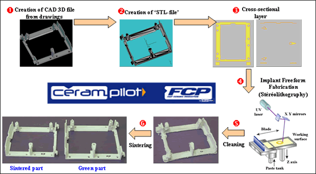
Fig. 1: Synoptic of the stereolithography ceramic part process. Example of alumina ceramic holders.
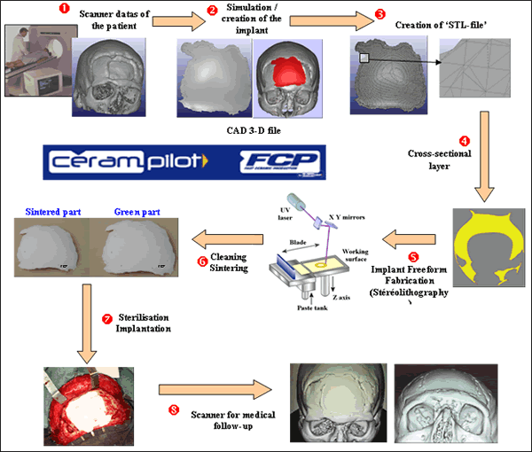
Fig. 2: Synoptic of the stereolithography ceramic part process. Example of human facial implant.
First, the CAD data of the part is converted to .STL file format, which is a standard interface between 3-D CAD models and the RP systems. The .STL file consists of facets of triangles that describe the surfaces of a closed 3D-CAD model. While stereolithography is based on a layered manufacturing procedure, the model is decomposed into cross-sectional layers and the conditions (trajectories, speed, laser power…) are generated to build up the cross-sectional patterns in each layer.
Using CAD information, laser beam radiation, focused on the top surface of the deposited paste, is deflected by galvanometric mirrors to harden the cross-sectional pattern and to bond subsequent layers. Then, the elevator table is moved down a layer thickness and a subsequent layer is deposited to continue the manufacturing process. This procedure is repeated until the part is built. Green parts are then cleaned from non-polymerized suspension, debinded and sintered (fig. 2 and 3). The range of shrinkages is 15 to 25 %.
Contrary to the classical stereolithography equipments, where a fluid monomer is required, the method developed here uses a paste with a high viscosity. The ceramic paste is introduced in a piston, which deliver a controlled quantity on the working area. Homogeneous layers, with different (from 10 to 500 µm) and smooth surfaces were spreaded by means of an adequate device before polymerization (Fig 3).
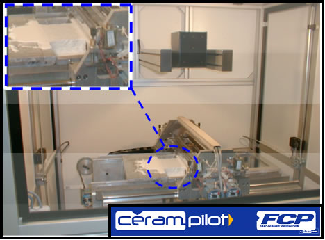
Fig. 3: Cerampilot ceramic stereolithography machine.
Characteristics:
-
Working area: 250 x 250 x 250 mm
-
Thickness of the layers: 10 to 500 µm
-
Precision: 1%
-
Manufacturing speed: 100 layers/hour
Research and development concerning the ceramic stereolithography, performed at SPCTS and Cerampilot, are summarized in figure 4, and can be divided into three main categories:
-
Comprehension of different physicochemical phenomenon involving during the process
-
Optimization of the formulations and of the process.
-
Characterization
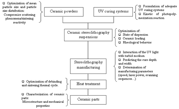
Fig. 4: Research topics
Several results:
i )Rheological behavior of ceramic stereolithography suspensions
The rheological behavior of high loaded ceramic systems was optimized, by means of adequate additives 9 , 10 , 11 , to allow suitable layer spreading and to achieve homogeneous green microstructure. A high yield value prevents non-insulated surfaces from flowing during the building of the piece. A shear thinning behavior allows the deposition of homogeneous layers with a thickness as low as 10 µm.
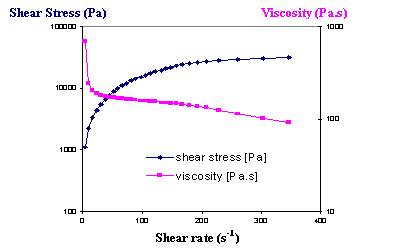
Fig. 5: Rheological behaviour of the alumina stereolithography paste.
(Alumina mean particle size: d50=1.5 µm ; Loading: 60 vol%)
In the example of alumina with a mean particle size of 1.5 µm (fig. 5), the measured viscosity, at a shear rate of 100 s-1, is 150 Pa.s, compared to a value larger than 1000 Pa.s at rest.
ii) Cure depth and width
Two key parameters have to be controlled in the ceramic stereolithography process:
-
Cure depth. The goal is to ensure a sufficient cured depth, even at high scanning speed, to avoid a too long time of fabrication.
-
Cure width, which directly influences the dimensional resolution.
The evolutions of the cured depth and width, in function of the energy density, for alumina, silica and zirconia powders, are given in figure. 6.
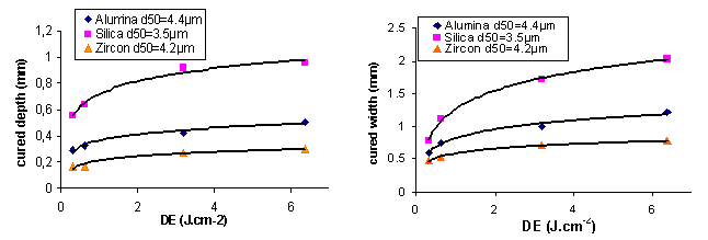
Fig. 6: Cured depth and width versus density of energy (DE) for alumina, silica and zirconia suspensions. 50 vol% powders loading.
A cure depth, varying from 180 to 600 µm, for a 50 vol% loaded system can be achieved for a low density of energy (DE) of 0.32 J.cm-2. The cure width is always larger than the laser beam diameter (120 µm), which is due to the scattering phenomena, caused by the presence of ceramic particles. In the example of alumina with a 4.4 µm mean particle size and for a cured depth of 300 µm (DE = 0.32 J.cm-2), the polymerisation width (about 600µm) is 5 times larger than the laser beam diameter.
A high cured depth requires a high density of energy whereas a high resolution requires a low density of energy. Then, the curing conditions can be different for each area of one cross-sectional layer according to the required accuracy of the considered area. For instance, a low density of energy (high dimensional resolution) can be imposed for the skin, whereas, a higher density of energy could be chosen for the bulk.
The ceramic parts manufactured by stereolithography have sintered properties similar to those obtained by classical processing techniques. The parts are nearly fully densified (alumina: d/dth = 97%, zirconia: d/dth = 99 %, hydroxyapatite: d/dth = 98 %) with a fine-grained microstructure (Fig. 7).
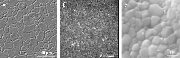
Fig. 7: Sintered ceramic stereolithography’s parts microstructure.
a – Alumina sintered 180 minutes at 1580 °C
b – Zirconia sintered 120 minutes at 1400 °C
c – Hydroxyapatite 60 minutes at 1200 °C
The mechanical properties of sintered parts are similar to those obtained by a classical shaping routes such as classical dry pressing.
Some characteristics on ceramics achieved by stereolithography process are given in table 1.
|
purity |
density |
3-points flexural strength |
|
|
Alumina |
> 99,8 % |
> 98 % |
275 MPa |
|
Zirconia |
> 99,9 % |
> 99 % |
1100 MPa |
|
HA |
> 99,9 % |
> 98 % |
75 MPa |
Tab 1: Properties of ceramic parts achieved by stereolithography process.
The various ceramic parts, elaborated by stereolithography, have proved their importance in major activity sectors. As shown by some examples of applications cited below, the possible elaboration of parts is virtually limitless, whatever the shape complexity.
-
Biomedical: Maxillo-facial and cranial implants in hydroxyapatite (BIOCERARP project)
The aim of the project is to elaborate Custom-made bioceramic implants by stereolithography, with 3D file obtained directly from data scanner patient. The project is based on implants study and realization for cranio and maxillo facial surgery.
The technique actually developed allows bioactive long-term implant manufacturing adapted on the patient morphology and conform to the surgeon demand, eliminating so the necessity of a graft. It will allow as well reducing operation and hospitalization time of the patient.
A porous structure intended is to enhance bone anchorage (surface) and bone growth (volumic) in/on implant. These structures are directly included in the design of the implant before manufacturing (Fig. 8).
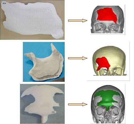
Fig. 8: HAP implants.
-
Telecommunication
In partnership with CREAPE INGENIERIE (Center of transfer specialized in antenna design, Limoges, France), LASMEA (laboratory specialized in electromagnetic compatibility, Clermont-Ferrand, France) and XLIM (Limoges, France), new ceramics antenna architectures, called PBG (Photonic Band Gap), were developed using stereolithography (Fig 9).
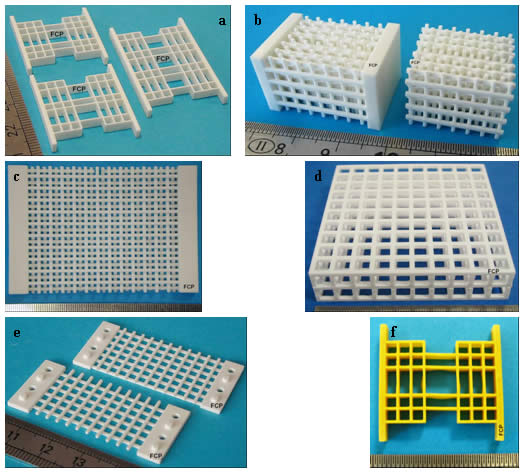
Fig. 9: Telecommunication SLA applications.
a, b, c, e) microwave filters (millimetre-length and terahertz) (sintered zirconia),
d) Periodic networks for photonic band antenna (sintered alumina).
f) microwave filters (millimetre-length and terahertz) (sintered BZT),
Characteristics of these structures are the existence of frequency bands for which waves can't be propagated (forbidden band). The introduction of defaults allows to obtain narrow domains for which information is transmitted.
The use of theses PBG structures opens new horizons in the conception of radiant systems, particularly the possibility to control the propagation of electromagnetic waves in a highly directive way.
Other fields are also interesting in this technology.
-
Aerospatiale and aeronautic
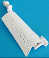
Fig. 10: Core in zircon/silica.
-
Electronics
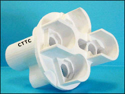
Fig. 11: Connectors (sintered alumina)
-
Metallurgy
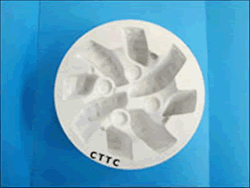
Fig. 12: Deep hole boring head mold (sintered alumina
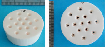
Fig. 13: Extruder die (sintered alumina)
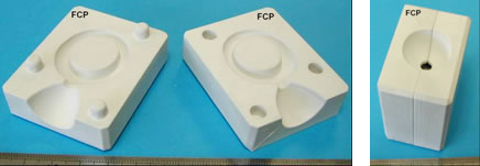
Fig. 14: Mold (green alumina)
-
Jewellery
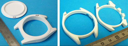
Fig. 15: Watchcases (sintered zirconia)
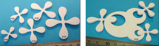
Fig. 16: Jewel (sintered alumina)
-
Optical field
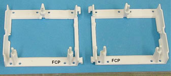
Fig. 17: Prism holders (sintered alumina
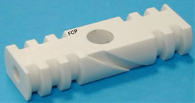
Fig. 18: Core for laser characterisation (sintered zirconia)
-
Analysis laboratory
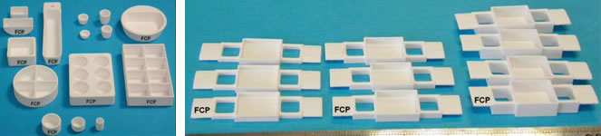
Fig. 19: Crucibles (sintered alumina)
-
Ceramic joints
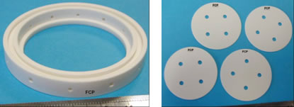
Fig. 20: Different joints (sintered zirconia)
-
Porous structures
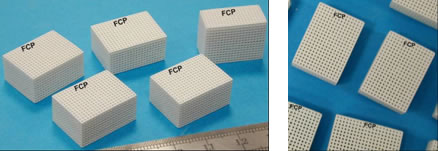
Fig. 21: Porous structures
-
Other fields
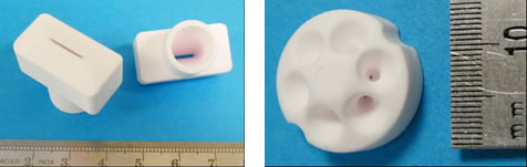
Fig. 22: Nozzles (sintered alumina)
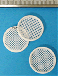
Fig. 23: Grid (sintered alumina
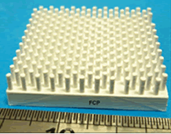
Fig. 24: Part of perforation (sintered alumina)
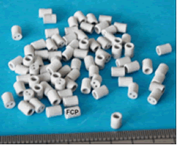
Fig. 25: Electric insulator (sintered aluminium nitride)
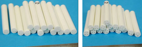
Fig. 26: Capillary (sintered zirconia)
Three-dimensional complex ceramic parts can be elaborated, with sintered properties similar to those obtained by classical processing techniques, using stereolithography as rapid prototyping method.
Highly concentrated curable ceramic systems (up to 50 vol.% powder) with suitable rheological behaviour and adequate UV reactivity were developed.
At present, the possible realization of parts is virtually limitless, whatever the shape complexity.
1. T. Chartier and C. Chaput, Shaping of ceramics by Solid Freeform Fabrication techniques. In Shaping II, ed. J. Luyten and J.P. Erauw, Flemish Institute for Technology Research, Belgium, 2002, pp. 249-258.
2. D. Klosterman, R. Chartoff, N. Osborne, G. Graves, A. Lightman and G. Han, Laminated Object Manufacturing (LOM) of advanced ceramics and composites. In Proceedings of the 7th Conf. On Rapid Prototyping, Un. of Dayton, San Francisco, CA, 1997, pp. 43-50.
3. A. Bandyopadhyay, R.K. Panda, V.F. Janas, M.K. Agarwala, S.C. Danforth and A. Safari, Processing of piezocomposites by fused deposition technique. J. Am. Ceram. Soc., 1997, 80, 1366-72.
4. K.A. Seerden, N. Reis, J.R.G. Evans, P. Grant, J.W. Halloran and B. Derby, Ink-jet Printing of wax-based alumina suspensions, J. Am. Ceram. Soc., 2001, 84, 2514-2520.
5. J.E. Grau, J. Moon, S. Uhland, M.J. Cima and E.M. Sachs, High green density ceramic components fabricated by the slurry-based 3DP process. In Proceedings of the Solid Freeform Fabrication Symposium. ed. J.J. Beaman, H.L. Marcus, D.L. Bourell, J.W. Barlow and T. Crawford. Un. of Texas, Austin, Texas, 1997, pp. 371-378.
6. K. Subramanian, N. Vail, J. Barlow and H. Marcus, Selective laser sintering of alumina with polymer binders. Rapid Prototyping Journal, 1995, 1 [2], 24-35.
7. T. Chartier, C. Chaput, F. Doreau and M. Loiseau, Shaping of complex ceramic parts by stereolithography. In Ceramic Transactions, Vol. 112, Ceramic Processing Science VI, Am. Ceram. Soc., 2001, pp. 357-62.
8. T. Chartier, C. Chaput, Y. Abouliatim, C. Delage, Rapid Prototyping: Fabrication of Three-Dimensional Complex Ceramic Parts by Stereolithography. CFI, Ceramic Forum International, 83, 2006, E102-E108
9. Transfert de Technologies (FR), C. Chaput, T. Chartier, F. Doreau, Ceramic paste composition and prototyping method, Patent N°: WO0042471, 2000.
10. Centre de transfert de Technologies (FR), C. Chaput, T. Chartier, F. Doreau, A ceramic paste composition for stereophotolithography for the production of dental bridges, Patent N°: FR2835827, 2003.
11. Centre de transfert de Technologies (FR), C. Chaput, T. Chartier, F. Doreau, Method and composition for making ceramic parts by stereolithophotography and use in dentistry, Patent N°: US2005090575, 2005.
Thierry CHARTIER
SPCTS
UMR CNRS 6638 ENSCI
47-73 Avenue Albert Thomas
87065 Limoges cédex
E-mail :
t_chartier@ensci.fr
WEB:
www.encsci.fr
Christophe CHAPUT - Directeur Général
Centre de Transfert de Technologies Céramiques
Ester Technopole
BP 6915 LIMOGES CEDEX
tél. +33 (0)5 55 42 61 50
fax. +33 (0)5 55 42 61 55
E-Mail:
cttc@ceramic-center.com
WEB:
www.ceramic.center.com